Build and Verify a Ventilated Machine Enclosure Step by Step
A machine enclosure should be designed based on the machine’s operating requirements, not the other way around. Before work begins, a responsible person must review the machine supplier’s instructions, risk assessment, fire safety requirements, electrical specifications, emergency stop procedures, and service requirements. If the heat load, permissible temperature, or required airflow is unknown, the ventilation system must be sized by a qualified ventilation or mechanical engineer.
Step 1 – Measure noise, temperature, and airflow before construction begins
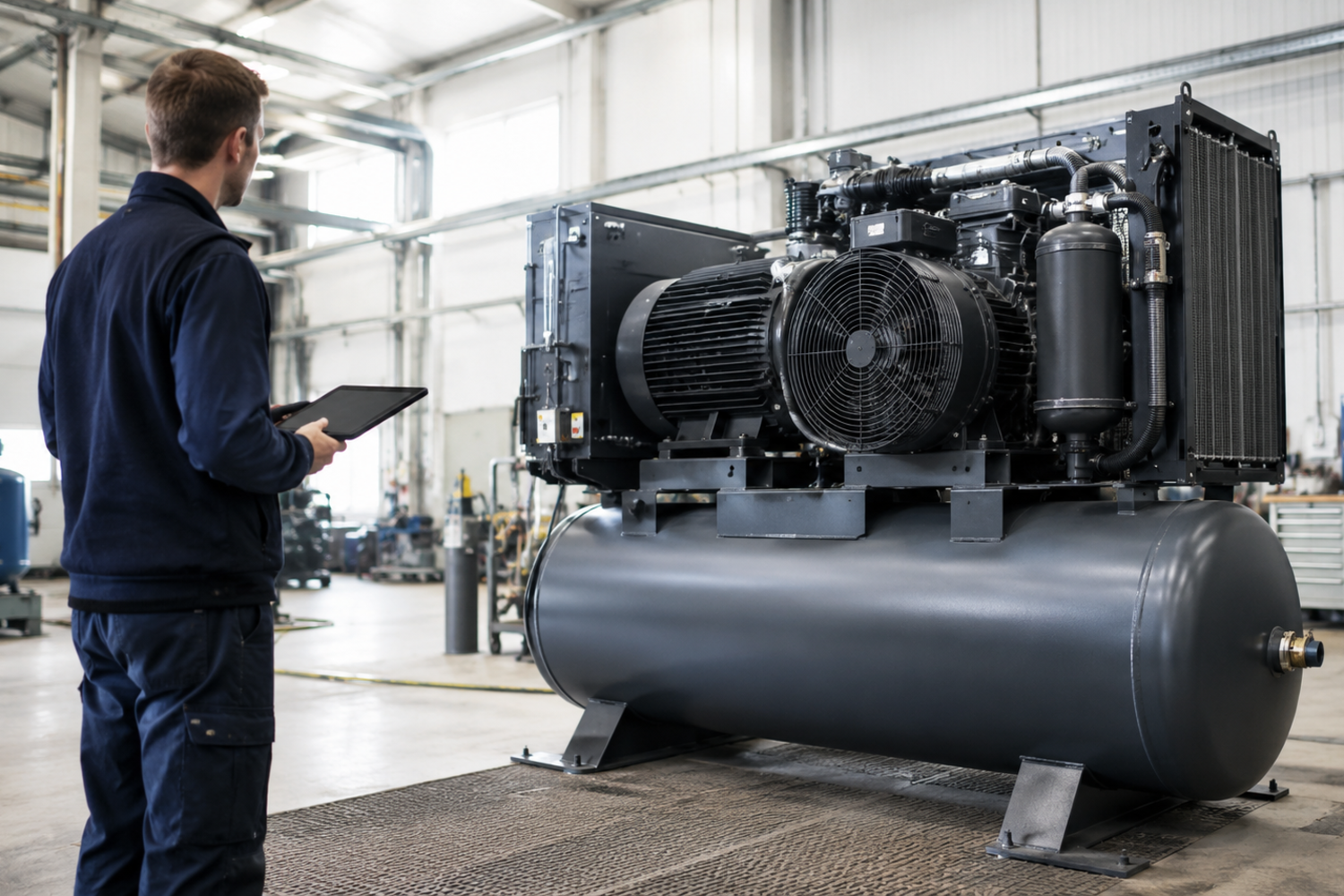
Document the machine’s operating conditions and identify the motor, fan, gearbox, pump, air intake, hot air outlet, and other distinct noise sources. Measure noise at fixed points around the machine and note whether the problem is dominated by airborne noise, sheet metal resonance, or vibrations in the floor and connections. At the same time, log the ambient temperature, intake air, and exhaust air under both normal and high representative loads. Save the measurement points so that the same conditions can be recreated after the intervention.
Step 2 – Determine Clearance, Heat Load, and Service Requirements
Sketch the machine’s actual external dimensions and add clearance for access panels, filters, belts, lubrication points, pipes, cable bends, and the removal of larger components. Ensure that emergency stop and shut-off controls remain accessible in accordance with the risk assessment. Calculate the required airflow based on the machine’s heat dissipation and the permissible temperature rise, and verify the result against the manufacturer’s documentation. Do not size the system based solely on the fan’s connection diameter. Filters, grilles, baffles, and ducts create pressure drops that must be included in the calculation.
Step 3 – Plan separate baffle ducts for supply and exhaust air
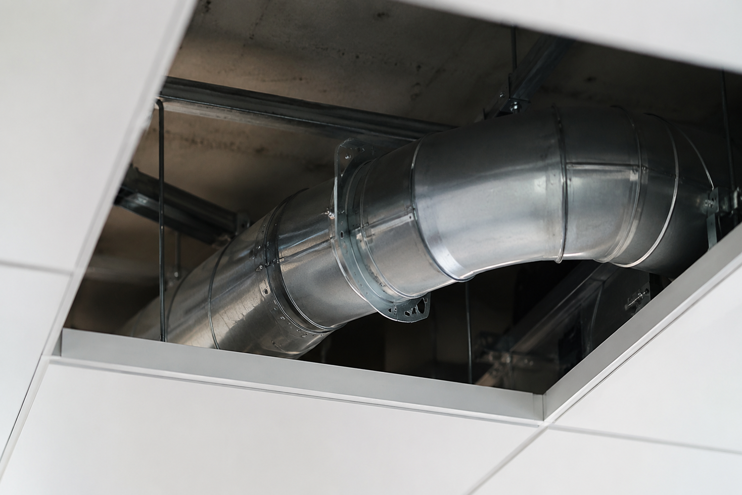
Place the supply air low or where the machine normally draws its cooling air, and the exhaust air near the hot zone, but always follow the machine’s intended airflow direction. Provide the ducts with a large free cross-sectional area and use multiple gentle changes in direction so that there is no direct line of sight from the noise source to the room. Avoid tight 90-degree bends, unnecessarily high air velocities, and locations where warm exhaust air can be sucked back into the system. If an auxiliary fan is needed, its capacity should be selected based on the system’s total pressure drop, and it should be installed so that it does not itself generate disruptive vibrations.
SilentDirect Air is a moldable sound absorber for ventilation ducts and installations where sound needs to be attenuated but airflow must still be maintained. Do not compress the material so that the calculated free area decreases uncontrollably, and leave the unit’s own intakes, outlets, sensors, and guards unobstructed.
Step 4 – Build a Rigid and Heavy Enclosure
Build a stable frame that does not come into direct contact with the machine. Select non-combustible or fire-rated panel and frame components in accordance with the site’s risk assessment. The enclosure must be continuous and sufficiently rigid to prevent resonance. SilentDirect MLV can be used in structures where high mass is needed to dampen airborne sound and leakage. On sheet metal, metal, and other hard surfaces where a thin barrier, sealing, and vibration damping are needed, SilentDirect Polaric may be appropriate. Always follow the product’s installation instructions and check surface temperature, substrate, and fire code requirements.
Step 5 – Decouple the frame, panels, and machine vibrations
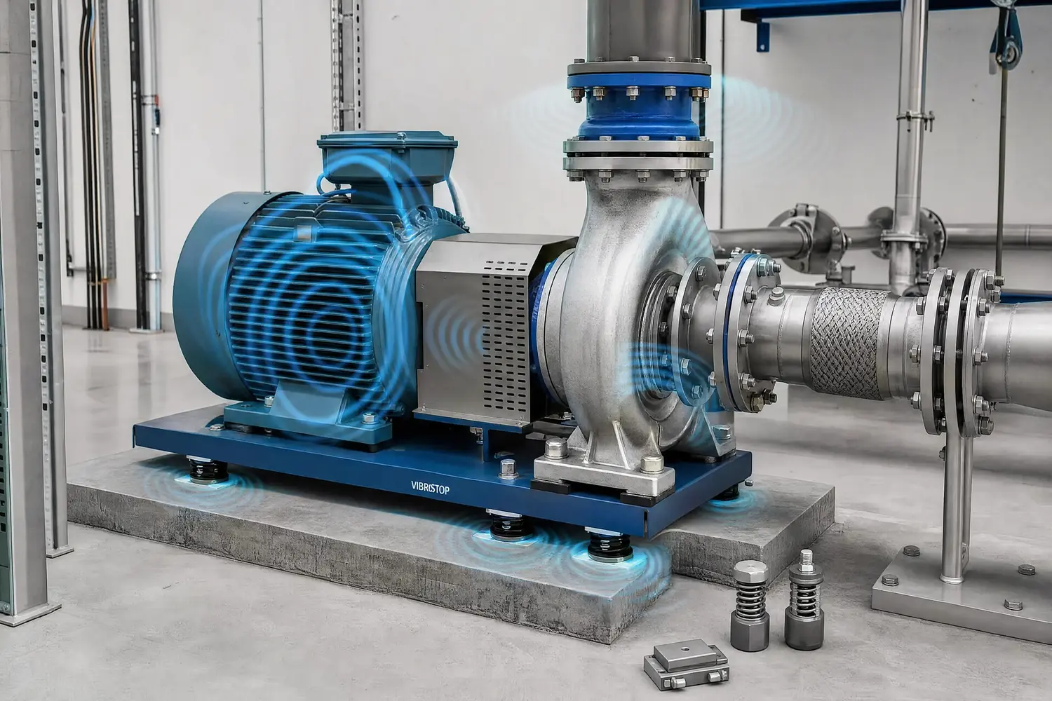
First, check whether the machine can be placed on vibration isolators and whether the load, center of gravity, and anchoring allow for it. Dampio PRO is designed for machine feet, pumps, and equipment that transmit vibrations down into the floor. It should be selected and positioned based on the specific machine’s load and stability requirements. Flexible connections may be needed for pipes, ducts, and cables to prevent them from short-circuiting the decoupling.
When working with sound insulation and vibration damping, one of the most important principles is to decouple materials from one another. If different building components are in direct contact with each other, vibrations, structure-borne noise, and sound energy can easily be transmitted through the structure. This applies, for example, when constructing a framing system for walls, ceilings, or floors.
To reduce this transmission, the parts of the stud frame that come into contact with other surfaces should first be fitted with a vibration-damping layer. Here, SilentDirect Seal is an effective option. The product is a sealing strip made of nitrile rubber (NBR) and is designed to reduce sound leakage, dampen vibrations, and contribute to a tighter, quieter, and more energy-efficient structure.
SilentDirect Seal is placed between the stud and the surfaces it would otherwise be in direct contact with, such as the floor, ceiling, an existing wall, or a new wall structure. This creates a decoupling between the materials. The stud then has no direct contact with surrounding surfaces, which reduces the risk of vibrations and structure-borne noise being transmitted through the structure.
The result is more effective sound insulation, as both sound leakage and vibration transmission are limited. By using SilentDirect Seal at joints and contact points, you can create a more controlled structure where sound energy does not spread as easily. This makes the solution particularly useful for soundproofing walls, ceilings, and floors where you want to achieve a quieter and more comfortable environment.
Step 6 – Install interior absorption without creating risks
Line suitable interior surfaces with an absorbent material that can withstand the specific environment and whose installation is supported by the product specifications. SilentDirect Egg is suitable for engine compartments, machine enclosures, and surfaces where a profiled foam structure can absorb sound. SilentDirect Neo is suitable for machines, vehicles, and enclosures where a smooth foam surface is needed to dampen resonance and mechanical noise. Install only on clean, dry, and smooth surfaces according to the instructions. Keep the material away from moving parts, unprotected hot surfaces, sparks, liquids, and areas where it could be sucked into fans.
Step 7 – Seal openings, joints, and penetrations
Install covers with an overlap, applying even pressure and ensuring a seal around the entire edge. Use SilentDirect Seal where gaps, joints, and contact surfaces need to be sealed or where vibration transmission needs to be reduced. SilentDirect Aluminum Sealing Tape is suitable for sealing joints, seams, and aluminum-clad transitions. Sealing should not be applied over designated ventilation openings, drainage, sensors, or safety features.
Check for leaks using at least two methods. With the light method, place a bright lamp on one side of the closed enclosure in a safe, powered-off state; visible streaks of light indicate where a joint or opening is not sealed. Using the pressure method, create a very slight, controlled overpressure or underpressure—within the enclosure’s and machine’s permissible limits—and then check for leaks using a thin strip of paper or a smoke pen designed for ventilation testing. Never use flammable smoke, an open flame, or pressures that could damage the machine.
Step 8 – Test run and verify both cooling and noise levels
Start with a short supervised run and gradually increase to a representative load. Log the temperature at the intake, critical machine components, and exhaust air. Check the flow direction, filters, pressure drop, fan noise, and ensure that hot air is not recirculating. Compare these values with the manufacturer’s specified limits and shut down the system if temperatures rise abnormally, an alarm is triggered, or airflow decreases.
Once operation is stable, repeat the noise measurement at the same locations, distances, and machine load as before construction began. Also listen for new sounds from panel resonance, auxiliary fans, or rigid connections. Document filter replacement intervals, cleaning, seals, and inspection points in the maintenance plan. The enclosure must be re-verified whenever the machine’s operation, cooling system, filter type, or load changes.